
Some electronic component equivalence can be deceiving. Simple parts like resistors have a huge number of suitable substitutes, but some components that appear simple based on specification are not so easily swapped for different parts. The wrong part swap can impact everything from EMC to reliability, which can certainly outweigh a part swap to reduce assembly cost.
Before you accept part swaps based on part descriptions alone, take a look at these part swap examples in DC/DC converters that can produce major impacts on reliability and EMC.
Before Swapping a Part, Know the Important Specs
Many components in a design rely on one or two specifications that are critical to functionality. However, you don't always find these core specifications in the part description on a distributor website. The specification is often buried in a graph or table in a data sheet, and it's the designer's responsibility to know that important specification.
There's one area of design where buried specifications factor heavily into reliability and functionality: DC/DC converters. While they perform a very simple function, and the schematics often look straightforward, simple component specifications can be the major factor that determines whether a system functions or fails. Here are some of the most common instances where part swaps in DC/DC converters suddenly go wrong.
Rectifying Diodes
Power electronics often need rectifying diodes to convert a pulse wave train or AC power into a pulsating DC output. For AC conversion, particularly with mains power, most diodes will work fine as long as they meet the voltage and current requirements. For DC/DC converters, it is not so simple due to the fact that pulses are often driven into an inductive element, which is then rectified and filtered to give the DC output.
In the case of rectifying pulses, diodes need to have very fast reverse recovery time. When the diode switches from forward conduction to reverse blocking, stored charge must be removed before the diode can fully turn off. Excessive reverse recovery time allows current to flow in the wrong direction during switching, which increases losses, creates larger voltage spikes, and can inject more noise into the converter. This specification limits the range of acceptable part swaps, and the wrong swap can lead to failure of the diode or another element in the design.
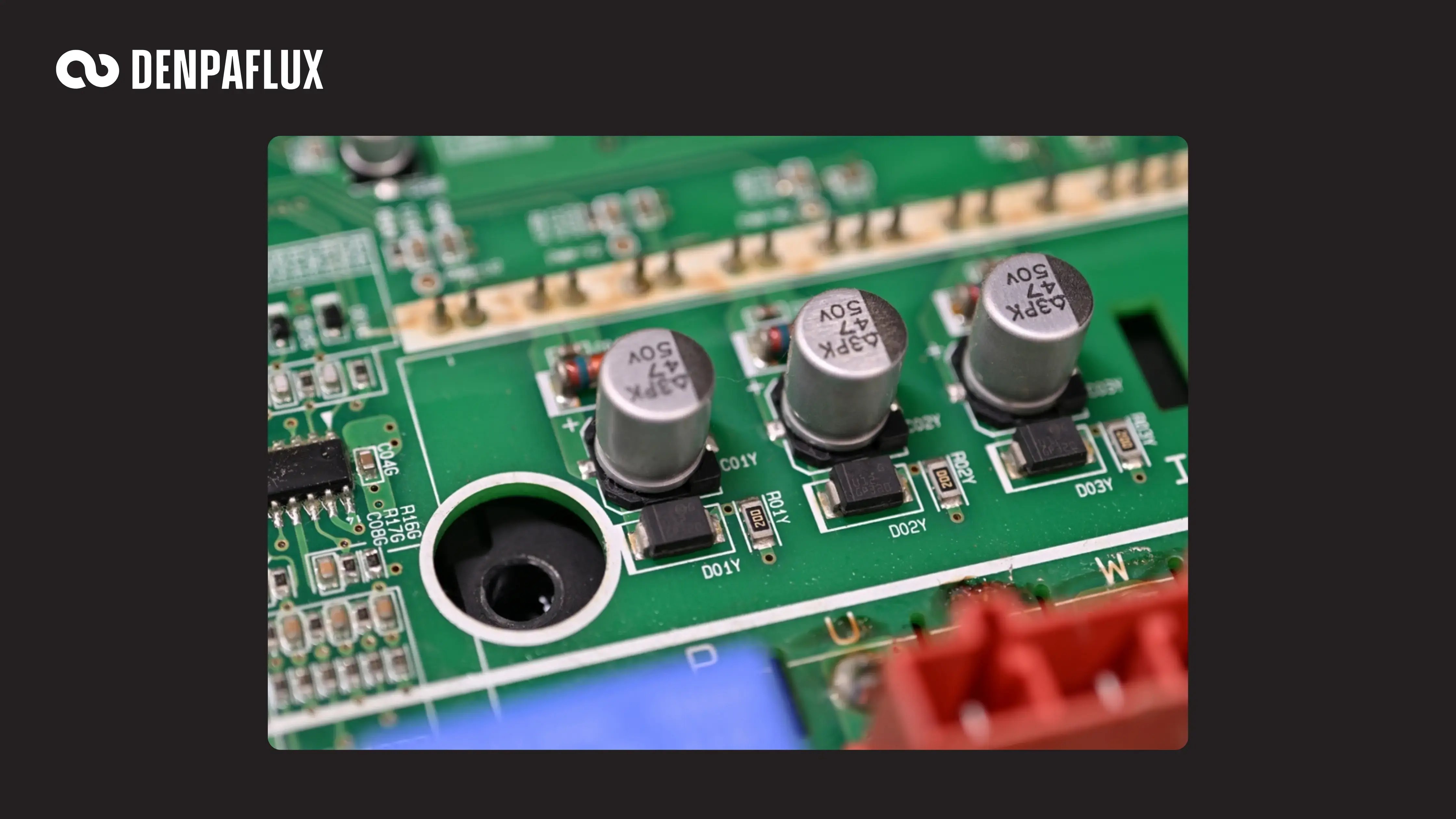 Rectifying diodes in a power supply.
MOSFETs in Switching Stages
MOSFETs in power systems are most commonly selected based on these specifications:
- Continuous source/drain current
- Peak pulse current
- Drain-source voltage
- Gate-drain voltage, or gate-source voltage for PMOS
For most simple applications, even applications handling pulses, most MOSFETs have no problem handling an arbitrary driving signal on the gate and delivering short pulses to a load. In power systems with a switching stage, the situation is different, as the allowed peak pulse current and on-time are related to each other and are a function of the applied gate voltage. This is defined using a safe operating area graph from a MOSFET data sheet. The MOSFET can only permit its maximum pulse current for a limited amount of time before the RDS(on) channel resistance dissipates enough heat to destroy the component. When swapping out MOSFETs in switching stages, this safe operating area graph needs to be examined and used to select the suitable alternate. Swapping simply based on voltage and current ratings, even for parts in the same package, can lead to failure of the alternate part.
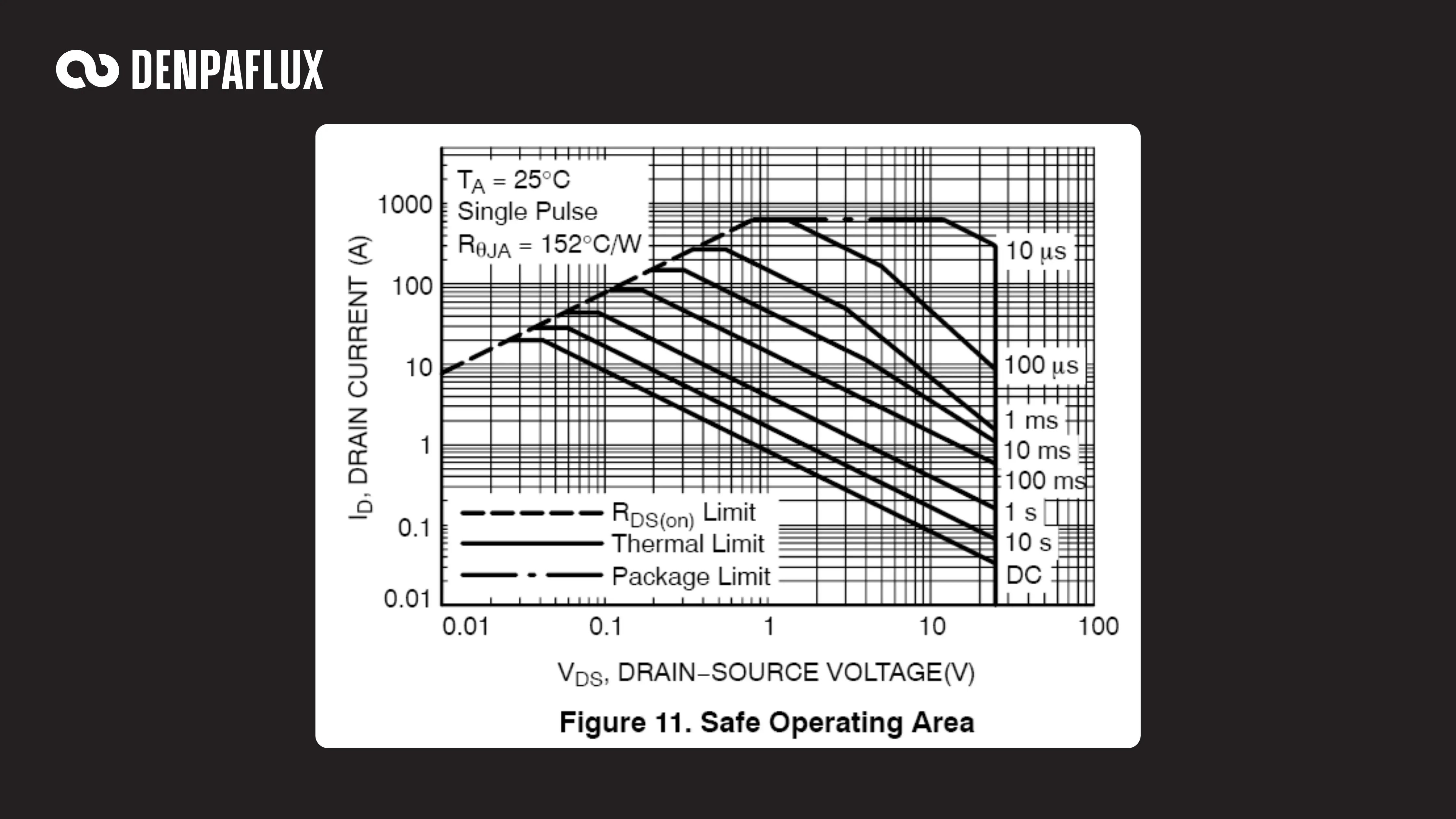 Safe operating area for part number NTTFS1D8N02P1E. [Source: ON Semiconductor NTTFS1D8N02P1E Datasheet]
Magnetic Core Inductors
Inductors with magnetic cores (not air filled) used in power stages generally have a current rating, but the current rating could mean two possible things:
- A temperature-based current rating that relates to power dissipation in the inductor
- A saturation current rating at which the inductor core achieves maximum magnetization
Inductors will typically saturate before they burn up at high currents, but the current rating given in an inductor part description may not distinguish between these two values. When the inductor saturates, it starts acting like a smaller inductor at higher field strength. If used in the output filter stage on a switching converter, this translates into larger current spikes and additional switching noise on the output. Make sure to check this specification in an alternate part before accepting a component swap.
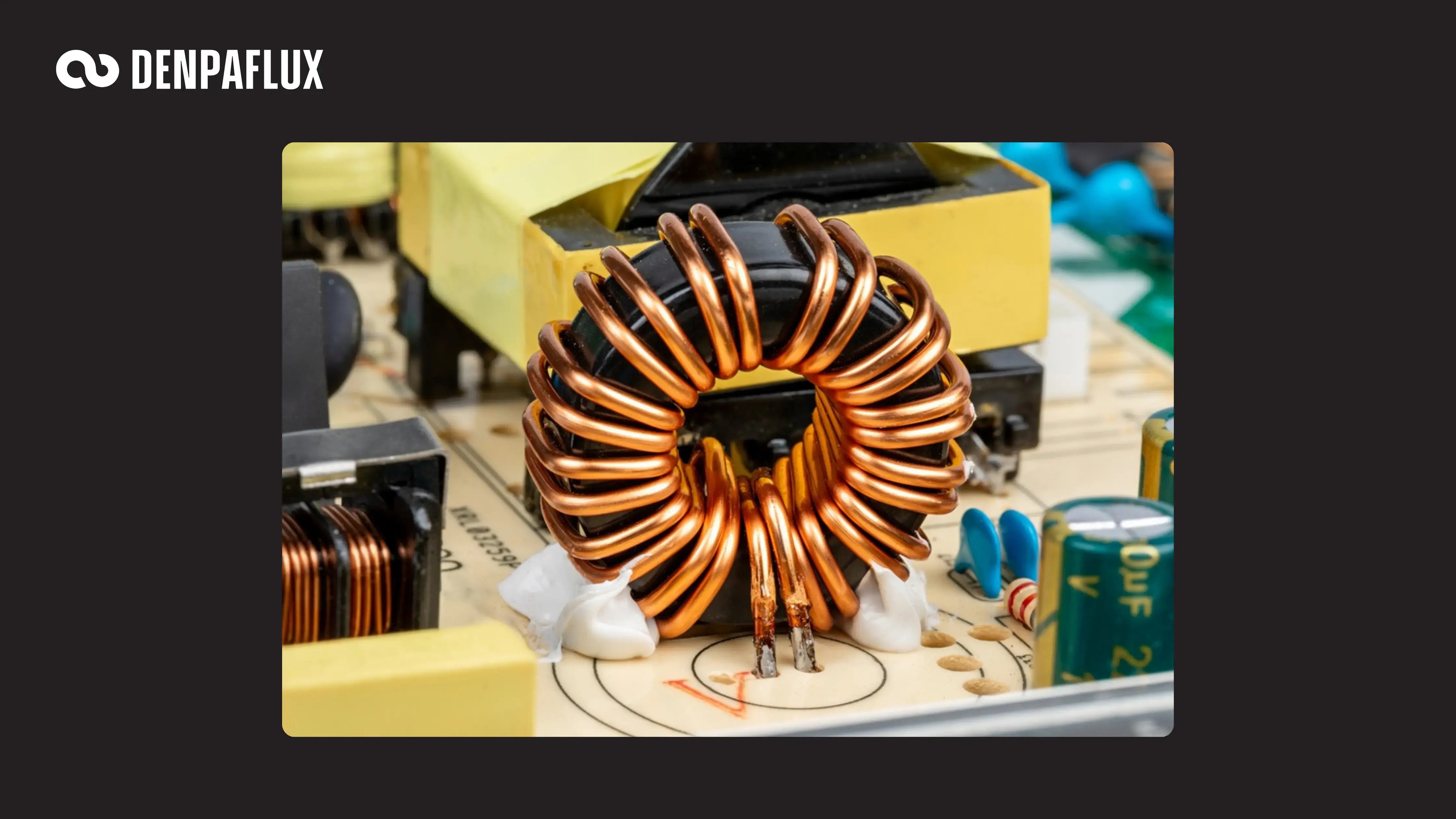 Magnetic core inductor.
Another option is to use an alternate core material when possible, such as switching from an iron core to a powdered core. This could allow similar inductance value and current handling, but with higher saturation limit or soft saturation during operation.
Safety Capacitors
A safety capacitor is used in an isolated DC/DC converter in three locations:
- As a series element in the input EMI filter (Class X)
- As a shunt element connecting to earth in the input EMI filter (Class Y)
- Connecting primary and secondary grounds across the transformer (Class Y)
The last of these three areas is where EMI and reliability can be impacted with an improper component selection. The capacitance of these components needs to be larger than the winding-to-winding capacitance of the transformer. This is necessary to control high-frequency noise currents passing between the ground nets.
The other specification that matters greatly is the voltage rating on the capacitor. Isolated DC/DC converters are normally specified based on a target withstand voltage, typically to meet some system-level requirement or an industry standard. When swapping out a Class Y safety capacitor, make sure the voltage ratings are preserved to ensure overall safety and compliance of the design.
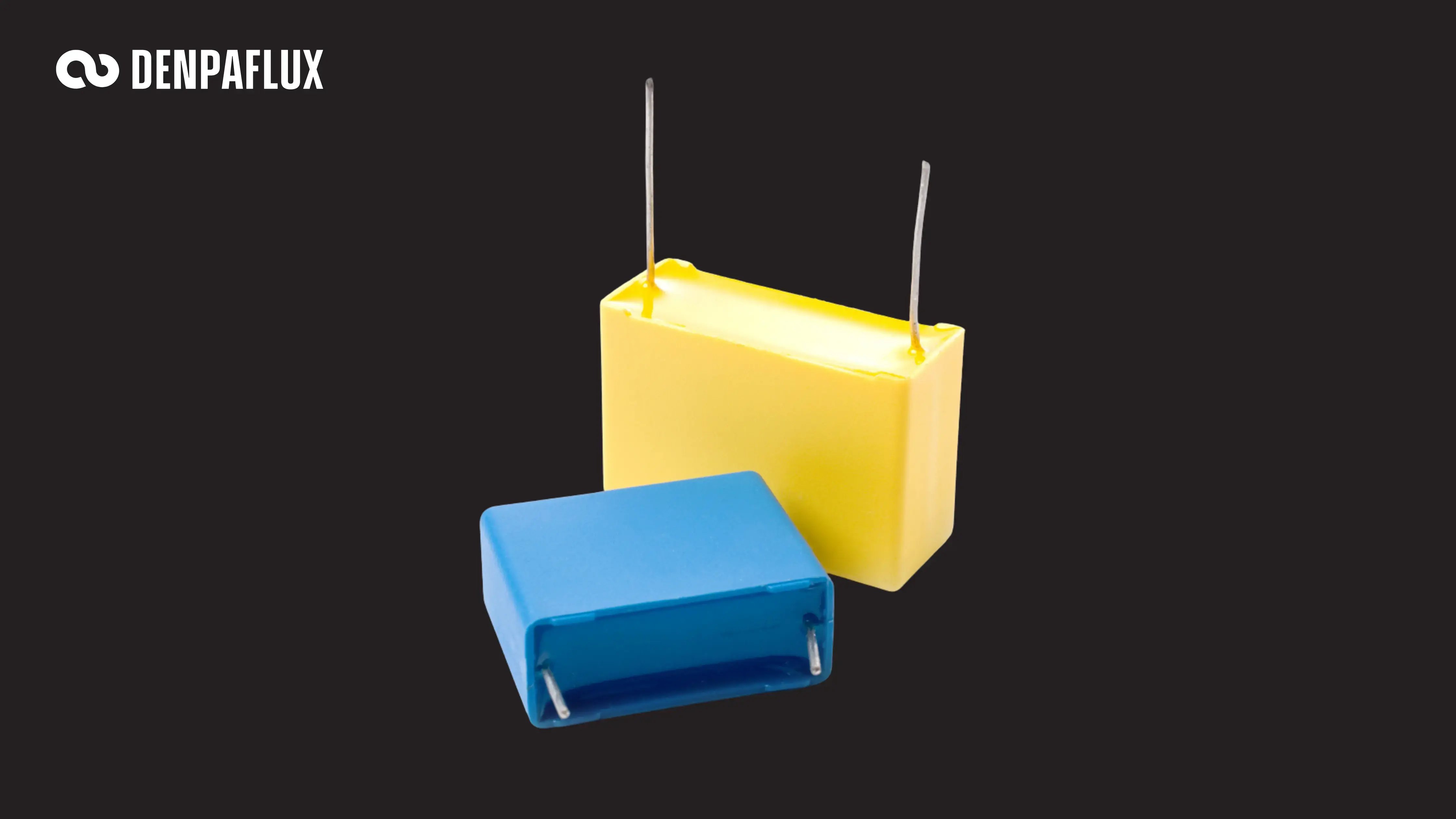 Safety capacitors in a power supply.
No matter which components you need to swap, the system should be analyzed for EMC risks before you commit to a board spin. DENPAFLUX helps designers analyze their PCB and system design to identify those risks. We review your layout against the industry standards and regional regulations that apply to your product, then return a report that pinpoints likely EMI sources with concrete recommendations for fixing them.
How much we take on is your call. Some teams want an independent expert review to validate their direction. Others want us validating every step as they implement, with formal sign-off before each test. And some want EMC handled end to end so they can stay focused on the product. Whichever fits where you are, the same team and the same diagnostic depth sits behind your project.


.png?width=352&name=EMC%20Design%20Tips%20for%20Medical%20Devices%20(1).png)