
.png?width=4480&height=2520&name=Should%20PCB%20Ground%20Cutouts%20Be%20Used%20With%20Chokes%20(1).png)
Ground cutouts or ground splits are usually a bad idea unless you know what you're doing. This is true in mixed-signal devices, RF devices, and power electronics. There's one area where a ground cutout is sometimes implemented, and that is in the use of a choke or filtering in AC circuits.
A choke can be used to pass AC or low-frequency DC while filtering high-frequency AC. They are magnetic components that essentially function as standard inductors over a broad frequency range. It is said that all chokes are inductors, but not all inductors are chokes, and an important difference between these components is their intended functions in a circuit.
When a choke is used in a circuit, should you add a ground cutout below the choke? This is sometimes a guideline that is recommended for chokes in a PCB layout, and the most common instance it is also recommended is to remove the ground plane below an inductor. We'll explore why this is unnecessary or why it may be a bad idea, depending on the frequency range where your device is operating.
Chokes and Inductors
As I mentioned above, all chokes are inductors, but not all inductors are chokes. The primary differences are the design of the component and the function in which it is used, which is enabled by the design. The difference can be summarized as follows:
- A single-ended choke is used as a first-order low-pass filter
- An inductor stores and releases energy
Of course, a choke also stores and releases energy, but it does this with the goal of providing a filtering function. Based on the specs in a datasheet, a magnetic component could be used as either an inductor or a choke; the only difference is the intended application. In fact, some datasheets use both terms to refer to the same component (see EPCOS part number B78108S1102K000). Also, some manufacturers do not distinguish between these parts, they call everything an inductor (Taiyo Yuden is one example).
Hopefully, this illustrates that the difference between chokes and inductors is mostly semantic, and it illustrates that the naming depends on the application where the component is used. This comparison of chokes vs. inductors is important because some power electronics guidelines state to remove ground below an inductor in a fast switching application, which is known to increase emissions. Would the same effect occur with a choke?
Should Ground Be Removed From Below a Choke?
My general guideline regarding placing ground cutouts below any component is as follows:
If you're unsure about whether to remove ground below any component, then don't do it.
A related simple guideline is:
"If you can't prove through measurements that a ground cutout provides a benefit in your application, then don't place the ground cutout."
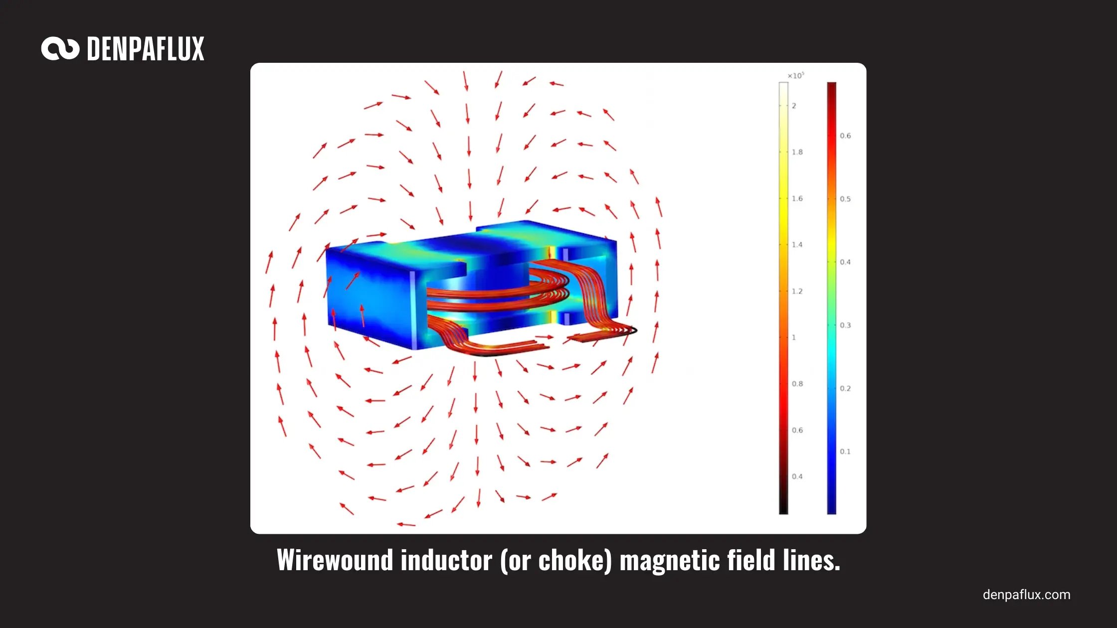
That being said, we have to understand how the ground cutout affects the rated inductance of the choke and the magnetic field around the choke. The magnetic field around a typical choke is shown in the image below.
As is the case with any components or printed circuit, the presence or absence of ground influences two factors:
- Stray capacitance between ground and the component, particularly the mounting pads
- The electromagnetic field distribution around the component, which influences EMI
Removing ground below a choke essentially eliminates any stray capacitance that is not already accounted for in the body of the choke. There is already winding-to-winding capacitance in a choke along its winding axis. This capacitance and the stray capacitance from the nearby ground influence the frequency-dependent behavior of the choke.
An ideal choke functions as an ideal inductor, but real chokes do not function this way. At sufficiently high frequencies, the stray capacitance takes over and provides a low-impedance path through the choke for high frequency signal/noise.
Typical component pads on a choke, capacitors, and other SMD components add less than 1 pF of stray capacitance to the components. The result is that one would expect a small deviation in the resonance frequency corresponding to the peak impedance. This creates very little impact on the transmission of the desired signal and very little impact on filtering of the broadband noise. However, removing the ground plane allows the magnetic field associated with the signal to emanate around the component and interact with nearby circuits. This is bad from the perspective of radiated emissions and noise coupling, the latter of which can lead to conducted emissions.

Comparison With Common Mode/Differential Chokes
Single-ended choke components are not the only way to filter noise. On coupled lines or differential pairs, we would use a differential-mode choke or a common-mode choke. Differential-mode chokes are normally used on power lines to eliminate noise measured between the two lines. A common-mode choke, or more generally a common-mode EMI filter, would be used to eliminate common-mode noise on data lines, including differential pairs.
These components can also be magnetic and will be impacted by the removal of ground from beneath them. The difference is that in these components, the windings in the choke are generally coupled with a shared core, which helps to confine the magnetic field in a toroidal arrangement. Still, these components have stray capacitance between the windings and with respect to a nearby ground plane.
Here are some factors relating to EMI and the usage of differential/common-mode chokes for coupled lines:
- With differential-mode chokes used on power, there typically is no ground plane and they are filtering down to a very low frequency
- Common-mode filters on data lines are intended to match impedance, which almost always requires a ground plane
- Manufacturers of these components typically don't state whether their test data was gathered with a ground plane
- Users often do not test or compare boards with or without a ground plane
DENPAFLUX RECOMMENDATION:
Given the heightened EMI risks and the lack of clear benefits of removing ground below a choke, it’s typically best to keep ground below a choke.
In some cases, like AC inputs, chokes are used alongside other filtering components without a ground plane as they are operating at very low frequency (60 Hz) with low noise spread across higher frequencies; in this case the lack of ground typically does not matter. There may also be a chassis ground which aids shielding of emissions.
In other cases, such as DC power coming into a system with a ground plane, the specific noise frequency range should be identified, and this often motivates the use of a particular choke or filter circuit. Typically one quickly finds that the ground cutout provides no benefit in these situations, it only creates a higher EMI risk and creates a region in the design where you cannot route signal traces.
To quickly analyze and identify potential sources of EMI in your schematics and PCB layout, look to Denpaflux for fast evaluation and qualification of your design. Denpaflux provides expert EMC reviews in 3 business days when you need fast guidance
or full EMC project delivery when you need to pass the lab on the first try.
To see how Denpaflux can help, contact an expert at Denpaflux to get started.


