

DO-160 Section 22 pin injection testing checks whether avionics interface circuits survive lightning-induced transients applied directly to their connector pins. For PCB designers, that makes it an interface protection problem: the protection network has to absorb the voltage, current and energy of the test waveform before it reaches the components behind the connector.
Lightning doesn't have to hit the equipment to damage it. When lightning strikes an aircraft, currents flowing through the structure and wiring induce transients on equipment interconnects, and those transients arrive at connector pins. A standard ESD diode array is rarely enough to stop them, because indirect lightning waveforms last far longer and carry far more energy than an ESD pulse. This guide explains the pin injection waveforms and levels, how they translate into protection requirements, and how to size a TVS diode and series resistor with a worked example.
What is DO-160 Section 22 pin injection testing?
RTCA DO-160, Environmental Conditions and Test Procedures for Airborne Equipment (published in Europe as EUROCAE ED-14), is the standard most avionics equipment is qualified against. Section 22 covers lightning-induced transient susceptibility, the indirect effects of lightning, while Section 23 covers direct effects. Section 22 defines two test approaches:
- Pin injection
- Transients are applied directly to designated connector pins, between each pin and case or chassis ground. Pin injection is normally used to show damage tolerance.
- Cable bundle tests
- Transients are induced into cable bundles and power leads by cable induction or ground injection. These tests are normally used to show upset tolerance, meaning the equipment keeps working during the transient.
During pin injection testing, the equipment under test (EUT) is normally powered, so interface circuits are biased as they would be in operation. For simple equipment, the aircraft manufacturer or certification authority may allow the test to run unpowered.
Section 22 requirements appear as a category code in the equipment specification. The first two characters cover pin injection: the waveform set (A or B) and the test level (1 to 5). For example, A3 means Waveform 3 and Waveform 4 at Level 3.
Pin injection waveforms and test levels
Pin injection uses three waveforms, grouped into two waveform sets. Set A combines Waveform 3 with Waveform 4, and set B combines Waveform 3 with Waveform 5A. Each waveform is defined by its open-circuit voltage (VOC) and short-circuit current (ISC). The ratio of the two gives the generator's source impedance, and together they set the energy the protection network has to absorb.
| Waveform | Shape | Level 3 | Level 4 | Source impedance | Main design concern |
|---|---|---|---|---|---|
| Waveform 3 | 1 MHz damped sine | 600 V / 24 A | 1500 V / 60 A | 25 Ω | Clamp response, parasitic inductance and both polarities |
| Waveform 4 | 6.4/69 µs voltage impulse | 300 V / 60 A | 750 V / 150 A | 5 Ω | Peak voltage and clamping voltage |
| Waveform 5A | 40/120 µs current impulse | 300 V / 300 A | 750 V / 750 A | 1 Ω | Peak current, pulse energy and heating |
Levels shown as VOC / ISC, from DO-160G, Table 22-2. RTCA's SC-135 committee has been preparing DO-160H with significant updates to Section 22, so always confirm the revision, waveform set and level called out in your equipment specification.
Waveform 5B, a longer 50/500 µs current impulse, is part of the cable bundle waveform sets rather than pin injection.
How to design interface protection for pin injection
The TVS diode is the main protection component, but it rarely works alone. Protection for a connector interface usually combines four functions:
- Series impedance
- Limits the current into the TVS diode and the downstream circuit. Use pulse-rated resistors, because a standard chip resistor can crack or fail open under a lightning pulse.
- TVS diode or other suppressor
- Clamps the remaining voltage below the damage threshold of the protected IC. Waveform 3 oscillates, so the protection has to handle both polarities, typically with a bidirectional device.
- Filtering
- Reduces high-frequency content where the interface bandwidth allows it.
- Return path
- Carries the diverted current to the intended circuit, case or chassis reference. Place the TVS diode close to the connector and keep its ground connection short, since every bit of inductance adds voltage on top of the clamping voltage during the fast edges of Waveform 3.
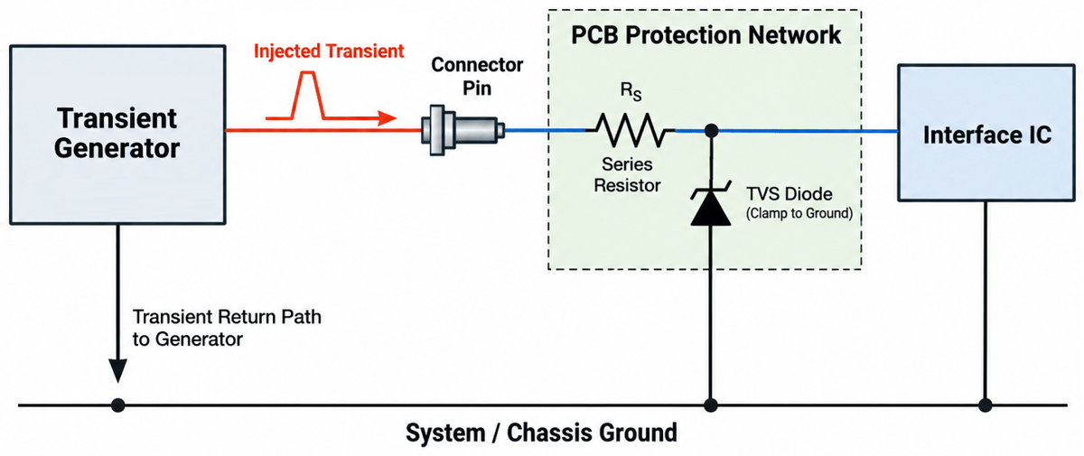
Three TVS datasheet parameters decide whether a part is suitable:
- Standoff voltage
- Above the highest normal signal or supply voltage on the pin, so the diode stays off during normal operation.
- Clamping voltage
- Below the voltage the protected IC can withstand, at the peak current the test will drive through the diode.
- Peak pulse rating
- Datasheets usually rate peak pulse current or power at 10/1000 µs or 8/20 µs. Use the derating curve for peak pulse power versus pulse duration to translate that rating to Waveform 4 or Waveform 5A.
Worked example: Level 3, Waveform 5A
Take an interface that has to pass waveform set B at Level 3, with a 10 Ω series resistor in front of the TVS diode and an IC that must stay below 40 V.
- Find the source impedance. Waveform 5A at Level 3 is 300 V open-circuit and 300 A short-circuit, so the generator's source impedance is 300 V / 300 A = 1 Ω.
- Calculate the peak current. With the protected node clamped to 40 V, the current through the protection path is (300 V − 40 V) / (10 Ω + 1 Ω) ≈ 24 A.
- Select the TVS diode. It needs a clamping voltage below 40 V at about 24 A, and a peak pulse current rating above 24 A for a pulse at least as long as 40/120 µs, checked against the derating curve.
- Check the series resistor. At 24 A, the 10 Ω resistor dissipates about 5.8 kW peak for the length of the pulse. Use a pulse-rated (anti-surge) resistor and confirm its pulse load rating for this waveform.
- Check Waveform 3 as well. Set B also includes Waveform 3 at 600 V / 24 A from 25 Ω. The peak current is lower, (600 V − 40 V) / (25 Ω + 10 Ω) = 16 A, but the pulse is faster and oscillates, so confirm the clamp response in both polarities.
Semiconductor vendors sometimes publish reference protection circuits for Section 22 levels. They're a useful starting point, but the circuit still has to be verified in your equipment, because the layout, parasitics and the real interface all change the result.
Verify the protection before qualification testing
Formal Section 22 testing is a costly place to find out that a resistor can't handle the pulse or a suppressor clamps slower than expected.
Circuit simulation with accurate component models helps narrow down candidate parts, and pre-compliance pin injection on prototype boards confirms the design while there's still room to change it. It's the same principle behind moving EMC upstream in product development: the earlier a problem shows up, the more options you have to fix it.
Aerospace designs demand maximum reliability, and that includes robust protection against indirect lightning transients. DENPAFLUX helps aerospace teams identify EMC risks in PCB designs before qualification testing, combining EMC engineering expertise with digital analysis tools. Our experts deliver a report with recommended solutions for complex EMI challenges.
Talk to an EMC expert
Get your aerospace PCB reviewed before qualification
Our EMC engineers assess the EMC risks in your design before DO-160 testing, so issues show up early, when they're still easy to fix.
Contact an expertFrequently asked questions
What is pin injection testing in DO-160?
Pin injection is a DO-160 Section 22 test that applies lightning-induced transient waveforms directly to an equipment's connector pins, between each pin and case or chassis ground. It is normally used to show that interface circuits are not damaged by indirect lightning effects.
What is the difference between pin injection and cable bundle testing?
Pin injection applies transients directly to individual connector pins and mainly shows damage tolerance. Cable bundle tests induce transients into the equipment's cable bundles and power leads and mainly show upset tolerance, meaning the equipment keeps operating during the transient.
Which waveforms are used for DO-160 pin injection?
Pin injection uses Waveform 3, a 1 MHz damped sine, together with either Waveform 4, a 6.4/69 µs voltage impulse (waveform set A), or Waveform 5A, a 40/120 µs current impulse (waveform set B). The test level, from 1 to 5, sets the open-circuit voltage and short-circuit current.
Can an ESD protection diode pass DO-160 pin injection?
Usually not on its own. ESD diodes are designed for very short pulses, while Waveform 4 and Waveform 5A last tens to hundreds of microseconds and carry far more energy. Most interfaces need a TVS diode rated for the waveform's pulse energy, often combined with pulse-rated series resistance.
Is the equipment powered during pin injection testing?
Normally yes, so the interface circuits are biased as they would be in operation. For simple equipment, the aircraft manufacturer or certification authority may allow unpowered testing.